Welcome to the fascinating world of P&ID drawing, where lines and symbols come together to tell the story of how pipes and instruments work in harmony. In this simple guide, we'll embark on a journey to demystify P&ID drawing (Piping and Instrumentation Diagrams) and make sense of the visual language used to represent the intricate dance of fluids and control in various industrial processes.
Whether you're a curious learner or a budding engineer, join us as we break down the complexities and unveil the simplicity behind P&ID drawing. Get ready to unlock the secrets of this essential tool that plays a crucial role in understanding and designing the inner workings of piping systems and instrumentation. Let's dive in!
What is P&ID Drawing (Piping & Instrumentation Diagrams)?
P&ID drawing, or Piping and Instrumentation Diagrams, is like a special map that shows how pipes and instruments work together in factories and plants. It's a simple way of using lines and symbols to tell the story of how liquids and gases move around, and how machines control them.
Imagine it as a guidebook for engineers and workers, helping them understand and design the complicated systems that make things run smoothly in industries like chemicals, oil, and more. So, P&ID drawings are like visual storytellers for the inner workings of these places!

What Does a P&ID Include?
When it comes to putting together a P&ID (Piping and Instrumentation Diagram), there isn't a strict set of rules, but a bunch of smart folks in the industry have shared some key things to include in a document called PIC001: Piping and Instrumentation Diagram Documentation Criteria. Here's a rundown of what you should have in a P&ID:
The Core Purpose of P&ID Drawings (Piping & Instrumentation Diagrams)
Design and Planning
During the initial design phase, P&IDs act as a foundation for conceptualizing and planning the entire process. They visually represent equipment, piping, instrumentation, and the flow of materials throughout the system, facilitating clear communication between engineers and other stakeholders.
Detailed Engineering
Once the basic concept is established, P&IDs become a roadmap for detailed engineering. They guide engineers in specifying pipe sizes, valve types, and control loop configurations, ensuring a well-functioning and efficient system.
Operation and Maintenance
P&IDs are an essential tool for plant operators to understand the normal operation of the process. They can quickly identify and locate equipment, piping, and instrumentation, allowing for efficient monitoring and troubleshooting. Furthermore, P&IDs are crucial for maintenance personnel, providing a clear picture of the system for repair and replacement tasks.
Training and Safety
P&IDs are valuable training aids for new plant personnel. By studying these diagrams, operators and maintenance staff can gain a comprehensive understanding of the system, promoting safe and efficient plant operation. Additionally, P&IDs can be used to identify potential hazards and develop safety protocols.
Key Benefits of P&ID Drawing in Engineering and Design
Piping and Instrumentation Diagrams (P&IDs) are more than just technical drawings; they are powerful communication tools that offer a multitude of benefits throughout the engineering and design lifecycle of a project. Let's explore five key advantages of utilizing P&IDs:
Enhanced Understanding of Processes
P&IDs act as a visual bridge, transforming complex processes involving piping, equipment, and instrumentation into a clear and understandable format. These diagrams depict the flow of materials, energy, and signals within a system, making it easier for everyone involved, from engineers to operators, to grasp the bigger picture. This fosters improved communication and collaboration among multidisciplinary teams, ensuring everyone is on the same page and can contribute effectively.
Improved Design and Engineering
P&IDs serve as the cornerstone for designing and engineering industrial facilities and systems. Engineers use them to plan and layout piping networks, select appropriate equipment based on process needs, and specify the necessary instrumentation for control and monitoring. By visualizing the system layout early on, P&IDs empower engineers to identify potential design flaws, optimize equipment placement, and ensure compliance with safety regulations and industry standards. This proactive approach minimizes costly rework and delays later in the project.
Effective Documentation and Standardization
P&IDs are invaluable documentation tools. They capture the design intent, equipment specifications, and operational parameters, serving as a permanent reference throughout a project's lifecycle. This ensures critical information is not lost or misinterpreted over time. Furthermore, P&IDs promote consistency and clarity by using standardized symbols, conventions, and nomenclature. This standardization allows engineers and other professionals to quickly understand P&IDs from different projects and organizations, streamlining communication and collaboration across teams.
Facilitated Maintenance and Troubleshooting
P&IDs are a maintenance crew's best friend. They provide a clear visual map of the system, allowing personnel to quickly locate equipment, valves, instruments, and their interconnections. This facilitates planning preventive maintenance schedules, conducting inspections, and troubleshooting issues efficiently. With P&IDs in hand, maintenance personnel can diagnose problems faster, minimize downtime, and keep the plant operational.
Compliance and Regulatory Requirements
P&IDs play a crucial role in ensuring compliance with regulatory requirements, industry standards, and safety codes. They document the process in a way that facilitates demonstrating adherence to environmental, health, and safety regulations. During audits, inspections, and regulatory approvals, P&IDs serve as clear and comprehensive documentation, providing a visual representation of the processes and systems that meet compliance standards. This can expedite the approval process and avoid costly delays.

P&ID Drawing Use Cases
Process System Development: Crafting the Roadmap to Success
P&ID drawings are the blueprints that streamline the design, implementation, and optimization of process systems. They provide a visual roadmap for engineers and operators, simplifying the complexities of pipes, valves, and instruments.
Ensuring Safety: A Visual Shield Against Hazards
Safety is paramount, and P&ID drawings play a crucial role in depicting safety-critical elements, emergency shutdown procedures, and material flows. In emergencies, these visuals become indispensable tools for quick decision-making and safeguarding both the plant and its personnel.
Management of Change: Navigating Transitions Smoothly
In the dynamic industrial landscape, change is constant. P&ID drawings facilitate the management of change, helping engineers and operators plan modifications effectively. They serve as living documents, evolving with the plant to ensure seamless transitions.
Plant Maintenance and Modifications: Keeping Operations Agile
During maintenance, P&ID drawings simplify tasks by providing a detailed snapshot of the plant's layout. Operators can efficiently identify components and understand their interconnections, reducing downtime and contributing to the overall longevity of the plant.

P&ID vs PFD (Process Flow Diagram)
Similarities
Differences
Limitations of a P&ID Drawing
P&IDs are like maps for factories, showing how machines work together. But they have some limitations:
Lack of Physical Detail
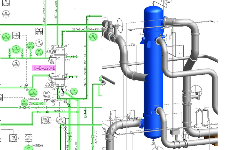
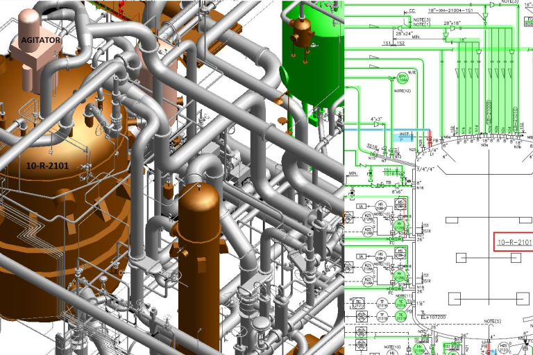
P&IDs are not drawn to scale and don't provide precise physical details about equipment placement or piping layout. While they depict the flow of a process, they don't necessarily reflect the actual physical space constraints within a facility. For detailed spatial planning, additional resources like 3D modeling software are necessary.
Limited Control Detail
P&IDs primarily focus on the process itself, with a basic representation of control loops. They may not capture the intricacies of complex control systems, including specific programming details or advanced control strategies. For a comprehensive understanding of control systems, additional documentation like control loop narratives or logic diagrams might be needed.
Potential for Misinterpretation
Standardized symbols are used in P&IDs, but depending on the level of detail and the experience of the viewer, there's always a possibility for misinterpretation. This highlights the importance of clear labeling, proper training, and using P&IDs in conjunction with other project documentation.
Limited Information for Maintenance and Repair
While P&IDs offer a general overview of the system, they may not provide all the specific details needed for maintenance and repair tasks. For technicians, additional resources like equipment manuals, spare parts lists, and maintenance procedures are crucial for efficient troubleshooting and repairs.
Focus on Functionality, not Safety
P&IDs prioritize depicting the process flow and functionality. While they might highlight safety-critical equipment, they may not comprehensively address all potential safety hazards within the system. For a thorough safety assessment, additional tools like Hazard Identification (HAZID) studies and Failure Mode and Effect Analysis (FMEA) are essential.
Even though P&IDs have these limits, they are still useful for understanding how a factory works. But sometimes, we need extra documents and tools to get the full picture.
Harmony AT’s P&ID Drawing Services
Harmony AT offers comprehensive P&ID drawing services to empower your engineering and design projects. Our team of P&ID specialists leverages their expertise and industry best practices to create clear, accurate, and efficient Piping and Instrumentation Diagrams. We deliver high-quality P&IDs that streamline communication, minimize errors, and meet project deadlines. Whether you require development of new P&IDs, updates to existing diagrams, or integration with 3D modeling software, Harmony AT has the experience and scalability to cater to your specific project needs. Let us transform your P&IDs into powerful tools that drive project success.
Contact Harmony AT today to discuss your P&ID needs and experience the difference our expertise and commitment to quality can make.
Danh mục


