3D CAD and 3D BIM can both create detailed digital models of buildings, structures, and infrastructure, making the two approaches seem similar on the surface. But a 3D model’s appearance alone does not tell the whole story. The way a model is created, the elements it contains, and how it is used within a project can lead to very different outcomes. So, if both 3D CAD and 3D BIM can represent the same project in three dimensions, where does the real difference begin?
3D CAD: Modeling the Geometry
3D CAD focuses primarily on creating and representing the geometry of a design. Instead of working only with 2D lines and drawings, designers can build three-dimensional objects that describe the form, dimensions, and spatial position of building components, structures, or other physical elements.

What a 3D CAD Model Represents
A 3D CAD model represents the physical geometry of a design through lines, surfaces, solids, and other geometric entities. These elements define characteristics such as shape, size, location, and spatial relationships. For example, a wall or structural component can be modeled as a precise 3D solid, allowing its dimensions and position within the overall design to be clearly represented.
The model can therefore provide a detailed geometric representation of a building or structure. However, what the model represents is primarily determined by its geometry and how the designer constructs the model.
What 3D CAD Is Typically Used For
In AEC projects, 3D CAD is commonly used for design development, detailed geometric modeling, visualization, and the preparation of design documentation. Designers and engineers can develop precise forms, examine spatial arrangements, and produce drawings based on the modeled geometry.
This makes 3D CAD effective for communicating the physical characteristics of a design. However, when a project requires the model to contain structured information about individual building elements, geometry alone is no longer the whole picture. This is where the modeling approach begins to move beyond 3D geometry toward Building Information Modeling.
3D BIM: Going Beyond Geometry
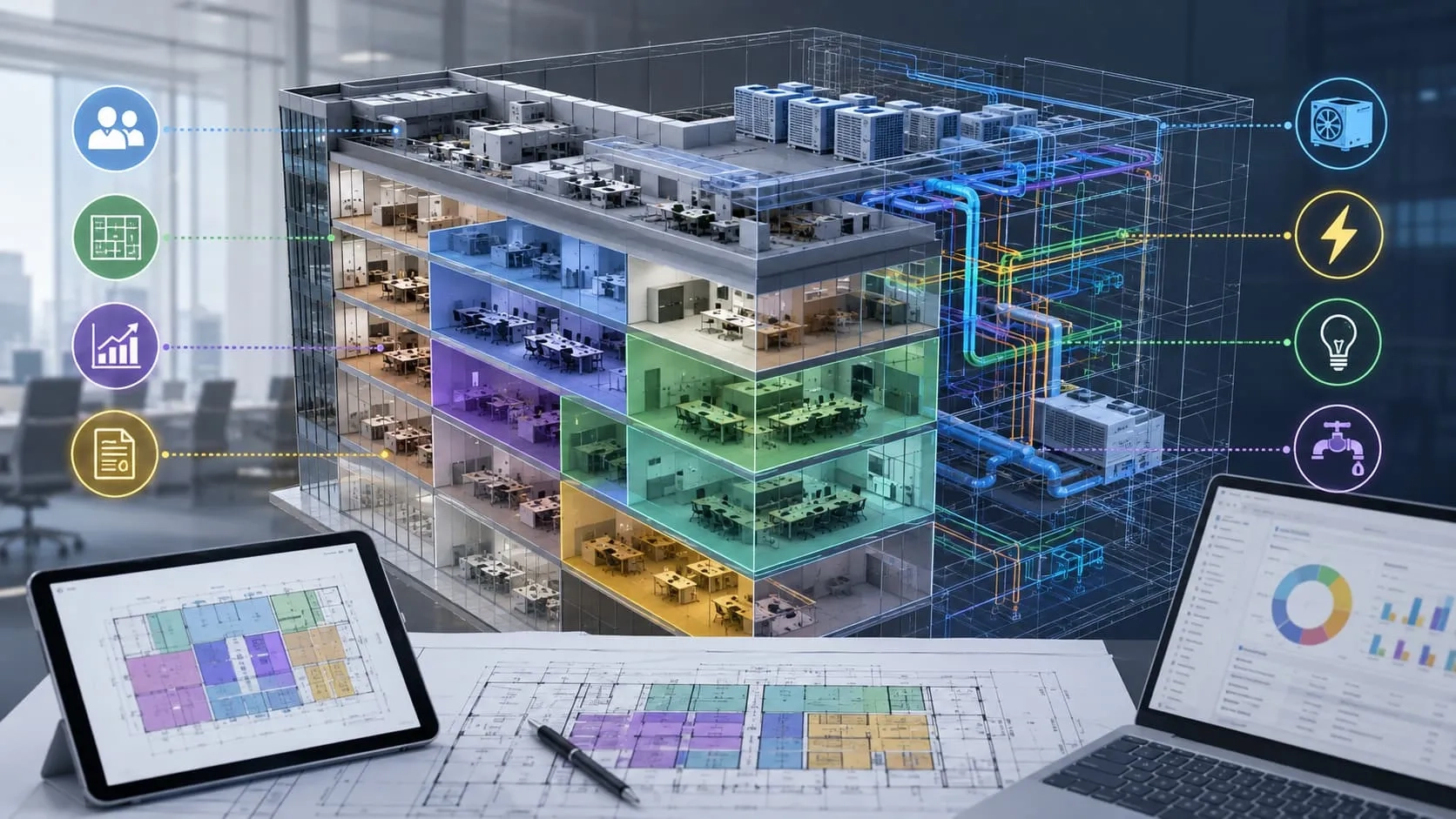
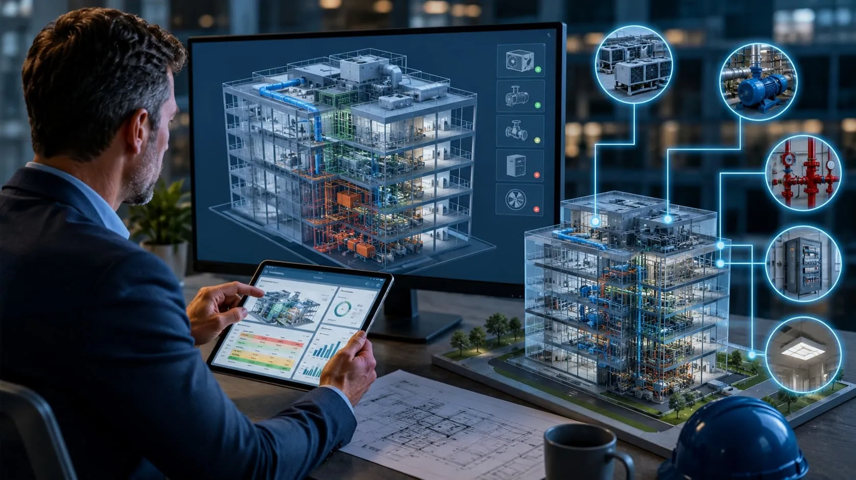
3D BIM also creates a three-dimensional representation of a project, but the model is not built around geometry alone. Instead, BIM uses model elements to represent actual building or infrastructure components and connects them with information that describes those components. This gives the model a structured meaning that goes beyond how an object looks in 3D.

From 3D Objects to Building Elements
In a conventional 3D model, an object can simply be a geometric shape created to represent part of a design. In BIM, the same geometry is associated with a specific project element. A wall is modeled as a wall, a door as a door, and a pipe or piece of equipment as a defined component within the project.
This distinction matters because the model is no longer just a collection of 3D objects. Each element has a role within the building or infrastructure being modeled, making it possible to understand what the element represents rather than only its physical form.
Adding Information to Model Elements
BIM elements can also contain structured information related to their physical and project characteristics. Depending on the project requirements, a door, for example, may include its type, dimensions, material, manufacturer, specification, classification, and other project parameters.
This information is associated directly with the corresponding model element, allowing the model to carry data alongside its geometry. The amount and type of information can vary according to the project stage, requirements, and intended use of the BIM model.
Connecting Elements Through Relationships
BIM also establishes relationships between model elements. A door can be associated with a wall, a pipe can connect to equipment, and a duct can be related to a space. Architectural, structural, and MEP elements can likewise be coordinated within the same project environment.
These relationships give the model a more complete representation of how the project is composed. BIM therefore goes beyond 3D geometry by giving model elements meaning, structured information, and relationships within the project.
3D CAD vs. 3D BIM: What Changes in Project Use?
The difference between 3D CAD and 3D BIM becomes more meaningful when the model is used throughout an AEC project. Both can support design in three dimensions, but they provide different ways of working with drawings, coordination, and project information.
Design and Documentation
With 3D CAD, the model primarily provides the geometric basis for developing and documenting a design. Drawings are created to communicate the design intent, dimensions, and physical characteristics of the project. When a design changes, related drawings or views may need to be reviewed and updated as part of the documentation process.
In BIM, documentation is more closely connected to the model and its elements. Plans, sections, elevations, schedules, and other views can be generated from the model, with information linked to the corresponding elements. For example, changing the properties or geometry of a modeled wall can affect the views and schedules that reference that element, depending on the project setup.
Coordination Across Disciplines
The difference is also apparent when architectural, structural, and MEP designs need to be coordinated. In a 3D CAD workflow, each discipline may develop its own drawings or models, and coordination involves comparing these separate design outputs to identify geometric conflicts and inconsistencies.
With BIM, discipline models can be linked or combined into a coordinated or federated model. Because elements are represented as defined project components, teams can review how a structural beam, HVAC duct, pipe, wall, or piece of equipment interacts with other elements. This supports model-based coordination and clash detection before issues reach the construction stage.
For infrastructure projects, the same approach can be applied to the coordination of road, drainage, utility, structural, and other design elements. Rather than reviewing each model only as separate geometric information, teams can assess how the different project components interact within the overall model environment.
Working With Project Data
3D CAD primarily provides geometric information that can be used to develop designs and produce documentation. Additional project data may exist in drawings, specifications, schedules, or separate systems rather than being directly structured within the 3D model.
BIM allows project information to be associated with individual model elements and extracted according to project requirements. Teams can use the model to generate schedules, obtain quantities, review specifications, and retrieve information about specific components without relying solely on their graphical representation.
This distinction becomes increasingly relevant when model information needs to support later project stages. Instead of using the model only to understand what has been designed, project teams can also use its structured information to support construction, handover, asset management, and other downstream activities.
Read more: When CAD Drawings Are No Longer Enough: It's Time for CAD to BIM Conversion
BIM Is Moving From an Option to a Project Requirement
BIM is increasingly becoming a defined requirement in AEC projects rather than simply an optional approach to 3D modeling. Depending on the market, project type, client, and procurement requirements, companies may be required to deliver BIM models that follow specific modeling standards, information requirements, and project workflows.
Harmony AT provides comprehensive BIM services for international projects, covering Architectural, Structural, and MEP BIM Modeling, CAD-to-BIM, Scan-to-BIM, BIM Coordination, and Model QA/QC. Our team can work from existing CAD drawings, design documents, point clouds, or project-specific BIM requirements to develop structured models for different project stages and deliverables.
Read more: Point Cloud to BIM for Renovation: Accurate As-Built Models that Cut Costs and Errors
With experience working with international clients and English- and German-speaking communication capabilities, Harmony AT can communicate directly with project teams, understand technical requirements and modeling standards, and coordinate BIM deliverables effectively. Whether you need complete BIM modeling support or additional capacity for a specific project stage, Harmony AT can work as an extension of your project team.
Categories